
 7.USB3.1 ultra high-speed Industrial Digital Cameras")
 7.USB3.1 ultra high-speed Industrial Digital Cameras")
 7.USB3.1 ultra high-speed Industrial Digital Cameras")
Jelly 6-MU3HS2001M(SRYYO) 7.USB3.1 ultra high-speed Industrial Digital Cameras
Introduction
Jelly6 series USB 3.0 ultra high-speed industrial digital cameras adopt the latest USB3.0 technology, high speed Sony sensor and 128M built-in hardware frame buffer. The speed is much faster than USB2.0 and normal USB3.0 digital cameras. The resolution ranges from 2.3MP to 20.0MP. These cameras have high sensitivity, high dynamic range, hardware frame buffer and high-speed features. Jelly6 series digital cameras can be widely used in machine vision and a variety of image acquisition areas.
Details
Overview
Packaging & Delivery
Packaging Details:Strong Carton with Polyfoam Protection
Port:Beijing
Lead Time:Within 1-2 Weeks after Receiving Payment
Introduction
Introduction
Jelly6 series USB 3.0 ultra high-speed industrial digital cameras adopt the latest USB3.0 technology, high speed Sony sensor and 128M built-in hardware frame buffer. The speed is much faster than USB2.0 and normal USB3.0 digital cameras. The resolution ranges from 2.3MP to 20.0MP. These cameras have high sensitivity, high dynamic range, hardware frame buffer and high-speed features. Jelly6 series digital cameras can be widely used in machine vision and a variety of image acquisition areas.
Features
1.Mirco USB3.1 high-speed interface, with maximum bandwidth of 5Gb/s, plug and play, no needof external power supply.
2.Mono/color industrial digital camera from 2.3MP to 20.0MP.
3.The hardware adopts FPGA+1Gb DDR3, enhancing frame caching technology to ensure high data transmission without losing frames. Multiple devices can synchronously collect data.
4.Supports GPIO optocoupler isolation for external triggering and flash control, with adjustable filtering and delay for external triggering signals.
5.Support multiple cameras to be used simultaneously.Users can customize camera serial numbers, and there is a dedicated read-write area for user parameters.
6.Support manual/automatic exposure, hardware white balance, CCM color correction, LUT lookup table, GAMMA lookup table, focus evaluation.
7.Provide KSJAPI development kit, including VC, C #, Halcon, Matlab, OpenCV, Python, QT, VB, VB.net, VisionPro democode.
8.Support third-party machine vision software interface controls such as DirectShow, Twain, Halcon, VisionPro, LabView, etc.
9.Support Windows XP/7/10 32bit&64bit systems, Linux X86/ARM 32bit &64bit systems, Android systems.
10.CNC machining high precision aluminum alloy shell, small size 29×29×30mm, weight 45g.
11.3m USB3.0 cable comes with fixing screws.
Application
Jelly6 series USB3.0 ultra high-speed industrial cameras are mainly designed for machine vision and high-speed image acquisition areas. They can be used for gel imaging, license image capture, medical diagnosis, microscopy imaging, notes image capture, Industrial production line image capture, fingerprint & palmprint image capture, desktop image, high speed vehicle license plate capture, outdoor monitoring, iris capture and etc.
Specification
|
Model |
MU3HS230M/C (SGYYO) |
MU3HI401M/C (IGYYO) |
MU3HS500M/C (SGYYO) |
MU3HS2000C (SRYYO) |
MU3HS2001M (SRYYO) |
|
Color/Mono |
Mono/color |
Mono/color |
Mono/color |
Color |
Mono |
|
Sensor Type |
CMOS |
CMOS |
CMOS |
CMOS |
CMOS |
|
Sensor Model |
SONY IMX174 |
ICRD ISG4006 |
SONY IMX250 |
SONY IMX183 |
SONY IMX183 |
|
Shutter |
Global |
Global |
Global |
Rolling |
Rolling |
|
Effective Pixels |
2.3MP |
4.0MP |
5.0MP |
20.0MP |
20.0MP |
|
Sensor Size |
1/1.2” |
1” |
2/3” |
1” |
1” |
|
Pixel Size |
5.86*5.86μm |
5.5*5.5μm |
3.45*3.45μm |
2.4*2.4μm |
2.4*2.4μm |
|
Max Resolution |
1936*1216 |
2048*2048 |
2464*2056 |
5472*3648 |
5472*3648 |
|
Frame Rate |
160fps |
83fps |
71fps |
18fps |
18fps |
|
Minimum Exposure Time |
17μs |
6μs |
26μs |
63μs |
63μs |
|
Image Output |
Micro USB3.1 Gen1, maximum bandwidth 5Gb/s |
||||
|
Power Supply |
USB3.1 Power Supply, 500mA@5V |
||||
|
Image Chache |
1Gb frame memory |
||||
|
Input/Output |
Opto-isolated GPIO, 1 channel external trigger input, 1 channel flash output, 1 channel 5V power supply input / output |
||||
|
Main Function |
Image display, image capture (bmp, jpg, tiff), video capture (compressor is optional) |
||||
|
Programmable Control |
Preview FOV ROI, Capture FOV ROI, SKIP/Binning mode, Contrast, Brightness, Saturation, Gamma value, RGB color gain, exposure, dead pixels remove, focus evaluation, custom serial number (0 to 255), white balance, LUT lookup table, CCM color correction |
||||
|
White Balance |
Auto / Manual |
||||
|
Exposure |
Auto / Manual |
||||
|
Image Format |
Support RAW8, MONO8, BAYER24, BAYER32 image preview acquisition, Jpeg, Bmp, Tiff image format saving |
||||
|
Operation System |
Windows XP/7/10 32 & 64bit, Linux X86/ARM 32 & 64bit system, Android system |
||||
|
SDK |
Provide KSJAPI development kit, including VC, C#, Halcon, Matlab, OpenCV, Python, QT, VB, VB. net, VisionPro demo code. Support DirectShow, Twain, Halcon, VisionPro, LabView third-party machine vision software |
||||
|
Lens Port |
Standard C-Mount |
||||
|
Working Temperature |
0°C~60°C |
||||
|
Storage Temperature |
-30°C~70°C |
||||
|
Camera Dimension |
29mm*29mm*30mm (W*H*L) |
||||
|
Camera Weight |
45g (High-precision CNC aluminum alloy shell) |
||||
|
Accessories |
Color cameras come with IR cut filter (mono camera does not have filter), 3m USB cable with fix screws, 6-pin Hirose GPIO connector, 1 CD with software and SDK. |
||||
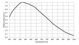
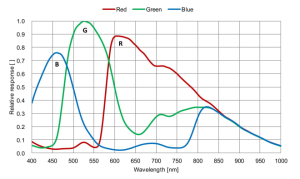
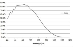
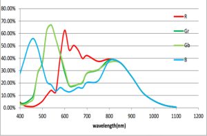
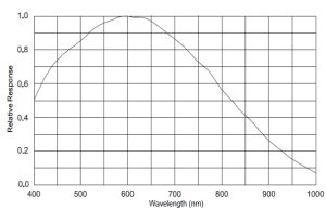
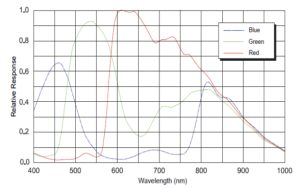
Spectral Response Curve
MU3HS230M (SGYYO)
MU3HS230C (SGYYO)
MU3HI401M (IGYYO)
MU3HI401C (IGYYO)
MU3HS500M (SGYYO)
MU3HS500C (SGYYO)
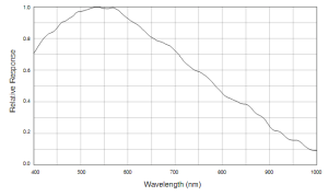
MU3HS2001M (SRYYO)
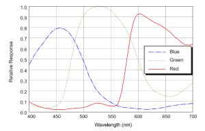
MU3HS2000C (SRYYO)
Dimension
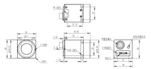
Unit: mm
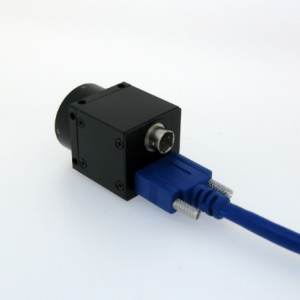
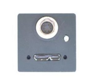
Interface
USB 3.1 USB Micro-B connector with screw lock
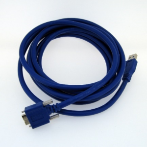
Recommend using a USB 3.1 Micro-B data cable with screw lock
Cable models that can be ordered:
USB3-M3M,USB3.0 Micro-B data cable with screw lock, 3 meters long
USB3-M5M, USB3.0 Micro-B data cable with screw lock, 5 meters long
USB3-M10M, USB3.0 Micro-B high flexibilitydata cable with screw lock, 10 meters long, built-in relay signal amplifier
USB2-M5M-AOC,USB3.0 Micro-B active hybrid fiber data cable with screw lock, 5 meters long, can be used for towing chains
USB2-M10M-AOC, USB3.0 Micro-B active hybrid fiberdata cable with screw lock, 10 meters long, can be used for towing chains
USB2-M20M-AOC, USB3.0 Micro-B active hybrid fiberdata cable with screw lock, 20 meters long, can be used for towing chains
Status indicator light
Determine the working status of the camera. If the red light is constantly on, it indicates successful hardware configuration and enters standby mode. If the green light flashes once, it indicates capturing one frame.
GPIO 6PIN connector
Camera GPIO connector specification: Hirose micro plug (HR10A-7R-6PB)
Recommended connector specification for GPIO cable: Hirose micro plug (HR10A-7P-6S)
Cable models that can be ordered:
Product model, specifications and parameters
EXT TRIGGER Cable-3M GPIO 6PIN data cable, 3 meters long
EXT TRIGGER Cable-5M GPIO 6PIN data cable, 5 meters long
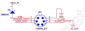
GPIO External Trigger interface introduction
|
Trigger Serial No |
1 |
2 |
3 |
4 |
5 |
6 |
|
Cable Color |
Red |
Black |
Yellow |
White |
Gray |
Brown |
|
Function Symbol |
5V_IN |
TRIGGER_IN |
USER_GPIO |
FLASH_OUT |
IO_GND |
GND |
Power Supply Input Interface
The camera is powered by USB3.0 Bus Power, the power supply of USB3.0 standard should be 5V@900mA. In actual applications, sometimes the host is not insufficient for power supply, or because the USB cable is too long, or because of anti-interference requirements, users can use “5V_IN” interface of GPIO to provide power supply for the camera. To ensure stable work of the camera, power requires DC + 5V, Min. = + 4.5V, Max. = + 5.5V; the drive current> 1A.
GPIO Input Interface
The following figure is the schematic diagram of GPIO input, the input signal has been insulated by opto-coupler TLP281. 200 ohm resistor is in series connection inside the camera. GPIO input interface is generally used for external trigger input signal synchronization acquisition for multi-camera, It also can be used as an external signal acquisition, please refer to the instructions in SDK (software development Kit) for detailed applications.
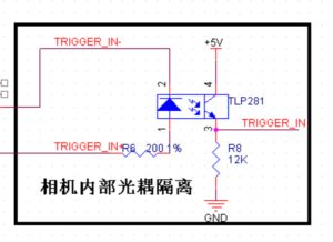
Internal Camera Opto-isolation
1.The camera’s internal optocoupler VCC = 5V, If IF = 16mA, then the external trigger input Rising edge Delay is 2us, Falling edge Delay is 40us;
2.When using “TRIGGER_IN +” as trigger source, the trigger electrical level range is +3V- + 6V.
3.If the trigger source electrical level is lower then 3V, will lead to a trigger signal loss;
4.If the trigger source electrical level is out of this range, an external current limiting resistor should be connected to make the optocoupler works around the typical current 16mA, otherwise the optocoupler will have risk of burning. If the trigger source voltage is 12V, need to connect external resistor in series about 1K, if the trigger source voltage is 24V, need to connect external resistor in series about 2.2K,
Limiting resistor is calculated as follows:
R = 100 x ( Vin – 0.7 ) – R0
Vin is Trigger source electrical level
R0 is The camera’s internal series resistor 200 Ohm
R is the required external series resistor.
GPIO Output Interface
The figure below is the schematic diagram of GPIO output interface, the output signal has been isolated through the optocoupler TLP281, coupled with an NPN audion to magnify drive capability; GPIO interface is generally used to output camera flash light signals, users also can output signal through SDK.
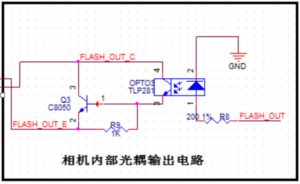
Internal Camera Opto Output Circuit
1.GPIO work as a normal IO output.
The following figure shows the ordinary connection when output interface work as normal IO output, the user needs to provide external power supply and pull-up or pull-down resistors.
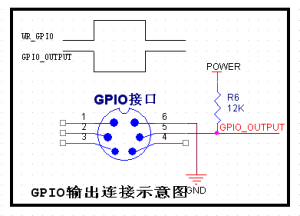
GPIO Output Connection Diagram
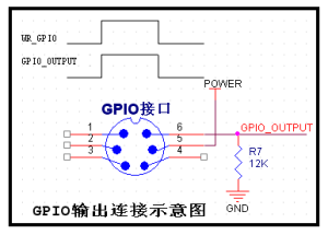
GPIO Output Connection Diagram
In the above figure, “POWER” is the power supply for the user, “WR_GPIO” is the output electrical level signal which is set by the user in SDK. “GPIO_OUTPUT” is the output signal, please note that the output electrical level of the 2 connections is just the opposite.
2.GPIO output to drive external load.
GPIO output interface is an open-drain output, it has certain drive capability to directly drive a small power device, as below figure, it is connected to 5V LED indicating light or low power flash lights.
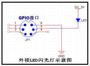
External LED flashlight Diagram
3.GPIO output interface connected with flash light controller.
The flash trigger interfaces of flash light controller are generally divided into the switch trigger and electrical level trigger; wire connection diagram is as follows:
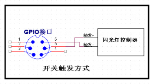
Switch Trigger Mode
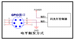
Electrical Level Trigger Mode
In the figure, “POWER” and “GND” are external power supply for the user, the electrical level should meet the interface requirements of flash light controller.
")