 USB2.0 Industrial Digital Camera")
 USB2.0 Industrial Digital Camera")
Jelly2-MUC320C (MRYYO) USB2.0 Industrial Digital Camera
Introduction
Jelly2 series smart industrial cameras are mainly designed for machine vision and image acquisition areas. The cameras are compact, occupy a small space, can be used on machines or solutions which have limit space. Resolution from 0.36MP to 5MP, speed up to 60fps, supporting global shutter and rolling shutter, supporting opto-couplers isolation GPIO, supporting multi-cameras work together, compact and light.
Details
Overview
Packaging & Delivery
Packaging Details:Strong Carton with Polyfoam Protection
Port:Beijing
Lead Time:Within 1-2 weeks after receiving payment
Introduction
Introduction
Jelly2 series smart industrial cameras are mainly designed for machine vision and image acquisition areas. The cameras are compact, occupy a small space, can be used on machines or solutions which have limit space. Resolution from 0.36MP to 5MP, speed up to 60fps, supporting global shutter and rolling shutter, supporting opto-couplers isolation GPIO, supporting multi-cameras work together, compact and light.
Features
1.The camera adopts USB 2.0 interface,up to 480Mb/s, which does not require external power supply and is plug and play.
2.Supports 36 to5 mega-pixel mono and color CMOS image sensors.
3.The hardware adopts FPGA+256Mb hardware frame cache, supports optocoupler isolation external triggering and flash control, ensuring synchronous image acquisition without losing frames.
4.Support multiple cameras to be used simultaneously. Users can customize camera serial numbers, and there is a dedicated read-write area for user parameters.
5.Support manual/automatic exposure, hardware white balance, CCM color correction, LUT lookup table, GAMMA lookup table, focus evaluation.
6.Provide KSJAPI development kit, including VC, C #, Halcon, Matlab, OpenCV, Python, QT, VB, VB.net, VisionPro democode.
7.Support third-party machine vision software interface controls such as DirectShow, Twain, Halcon, VisionPro, LabView, etc.
8.Supports Windows XP/7/10 32bit& 64bit systems, Linux X86/ARM 32bit & 64bit systems, Android systems.
9.Support firmware upgrade on-line.
10.CNC processed precision aluminum alloy shell, size is 29mm×29mm×30mm, net weight: 35g.
11.Board camera is available.
Application
Jelly2 series industrial cameras are mainly designed for machine vision and image acquisition areas. They are mainly used for following areas:
Medical and life sciences Area
1.Microscope Imaging
2.Medical diagnosis
3.Gel Imaging
4.Live Cell Imaging
5.Ophthalmology and iris imaging
Industrial Area
Electronics and semiconductor inspection
Visual positioning(SMT/AOI/Glue dispenser)
Surface defect detection
3D scanning machine
Printing quality inspection
Food and medicine bottles inspection
Robot welding
Tag OCR/OCV identification
Robot arm visual positioning
Industrial production line monitoring
Vehicle wheel alignment machine
Industrial Microscope
Road toll and traffic monitoring
High speed vehicle plate image capture
Public security and investigation
Biometrics
Fingerprint, palm print image capture
Facial recognition
License image capture
Documents and notes image capture and identification
Spectroscopy testing equipment
Specification
|
Model |
MUC36M/C (MGYYO) |
MUC120M/C (MGYYO) |
MUC120M/C(MRYYO) |
|
Sensor Model |
ONSemi MT9V034 |
ONSemi AR0135 |
ONSemi AR0130 |
|
Color |
Mono/Color |
Mono/Color |
Mono/Color |
|
Image Sensor |
CMOS |
CMOS |
CMOS |
|
Sensor Size |
1/3” |
1/3” |
1/3” |
|
Effective Pixels |
0.36MP |
1.2MP |
1.2MP |
|
Pixel Size |
6.0μm*6.0μm |
3.75μm*3.75μm |
3.75μm*3.75μm |
|
Max. Resolution |
752*480 |
1280*960 |
1280*960 |
|
Frame Rate |
60fps |
31fps |
37fps |
|
Exposure Mode |
Global |
Global |
Rolling |
|
Minimum Exposure Time |
17μs |
33μs |
33μs |
|
Scan Mode |
Progressive Scan |
Progressive Scan |
Progressive Scan |
|
Data Output |
USB2.0, 480Mb/s |
||
|
Power Supply |
USB2.0 Power Supply, 450mA@5V |
||
|
Image Chache |
256Mb frame memory |
||
|
Input & Output |
Optocoupler isolation GPIO, 1 of external trigger input, 1 of flash light output, 1 of 5V input/output |
||
|
White Balance |
Auto / Manual |
||
|
Exposure Control |
Auto / Manual |
||
|
Main Function |
Image preview, image capture (bmp, jpg, tiff), Video record (compressor is optional) |
||
|
Programmable Control |
Preview FOV ROI, Capture FOV ROI, SKIP/Binning mode, Contrast, Brightness, Saturation, Gamma value, RGB color gain, exposure, dead pixels remove, focus evaluation, custom serial number (0 to 255), white balance, LUT lookup table, CCM color correction |
||
|
Image Format |
Support RAW8, MONO8, BAYER24, BAYER32 image preview acquisition, Jpeg, Bmp, Tiff image format saving |
||
|
Operation System |
Windows XP/7/10 32 & 64bit, Linux X86/ARM 32 & 64bit system, Android system |
||
|
SDK |
Provide KSJAPI development kit, including VC, C#, Halcon, Matlab, OpenCV, Python, QT, VB, VB. net, VisionPro demo code. Support DirectShow, Twain, Halcon, VisionPro, LabView third-party machine vision software |
||
|
Lens Interface |
Standard C-Mount (CS and M12 mount are optional) |
||
|
Work Temperature |
0°C~60°C |
||
|
Storage Temperature |
-30°C~70°C |
||
|
Camera Dimension |
29mm*29mm*30mm (W*H*L) |
||
|
Camera Weight |
35g (CNC processed precision aluminum alloy shell) |
||
|
Accessories |
Color cameras come with IR cut filter (mono camera does not have filter), 2m USB cable with fix screws, 6-pin Hirose GPIO connector, 1 CD with software and SDK. |
||
|
Model |
MUC130M (MRYYO) |
MUC320C (MRYYO) |
MUC500M/C(MRYYO) |
|
Sensor Model |
ONSemi MT9M001 |
ONSemi MT9T031 |
ONSemi MT9P031 |
|
Color |
Mono |
Color |
Mono/Color |
|
Image Sensor |
CMOS |
CMOS |
CMOS |
|
Sensor Size |
1/2” |
1/2” |
1/2.5” |
|
Effective Pixels |
1.3MP |
3.0MP |
5.0MP |
|
Pixel Size |
5.2μm*5.2μm |
3.2μm*3.2μm |
2.2μm*2.2μm |
|
Max. Resolution |
1280*1024 |
2048*1536 |
2592*1944 |
|
Frame Rate |
30fps |
12fps |
9fps |
|
Exposure Mode |
Rolling |
Rolling |
Rolling |
|
Minimum Exposure Time |
10μs |
15μs |
17μs |
|
Scan Mode |
Progressive Scan |
Progressive Scan |
Progressive Scan |
|
Data Output |
USB2.0, 480Mb/s |
||
|
Power Supply |
USB2.0 Power Supply, 450mA@5V |
||
|
Image Chache |
256Mb frame memory |
||
|
Input & Output |
Optocoupler isolation GPIO, 1 of external trigger input, 1 of flash light output, 1 of 5V input/output |
||
|
White Balance |
Auto / Manual |
||
|
Exposure Control |
Auto / Manual |
||
|
Main Function |
Image preview, image capture (bmp, jpg, tiff), Video record (compressor is optional) |
||
|
Programmable Control |
Preview FOV ROI, Capture FOV ROI, SKIP/Binning mode, Contrast, Brightness, Saturation, Gamma value, RGB color gain, exposure, dead pixels remove, focus evaluation, custom serial number (0 to 255), white balance, LUT lookup table, CCM color correction |
||
|
Image Format |
Support RAW8, MONO8, BAYER24, BAYER32 image preview acquisition, Jpeg, Bmp, Tiff image format saving |
||
|
Operation System |
Windows XP/7/10 32 & 64bit, Linux X86/ARM 32 & 64bit system, Android system |
||
|
SDK |
Provide KSJAPI development kit, including VC, C#, Halcon, Matlab, OpenCV, Python, QT, VB, VB. net, VisionPro demo code. Support DirectShow, Twain, Halcon, VisionPro, LabView third-party machine vision software |
||
|
Lens Interface |
Standard C-Mount (CS and M12 mount are optional) |
||
|
Work Temperature |
0°C~60°C |
||
|
Storage Temperature |
-30°C~70°C |
||
|
Camera Dimension |
29mm*29mm*30mm (W*H*L) |
||
|
Camera Weight |
35g (CNC processed precision aluminum alloy shell) |
||
|
Accessories |
Color cameras come with IR cut filter (mono camera does not have filter), 2m USB cable with fix screws, 6-pin Hirose GPIO connector, 1 CD with software and SDK. |
||
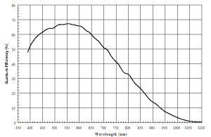
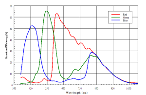
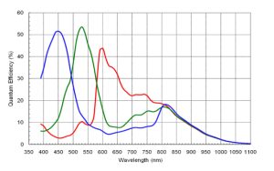
Spectral Response Curve
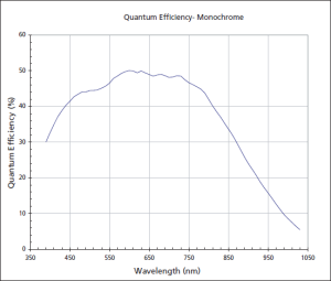
MUC36M (MGYYO)
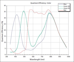
MUC36C (MGYYO)

MUC120M (MRYYO)
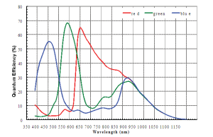
MUC120C (MRYYO)
MUC120M (MGYYO)
MUC120C (MGYYO)
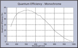
MUC130M (MRYYO)
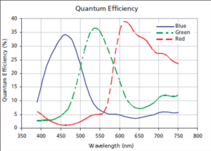
MUC320C (MRYYO)

MUC500M (MRYYO)
MUC500C (MRYYO)
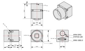
Dimension
Interface
USB 2.0 Mini USB connector with screw lock
Recommend using a USB 2.0 Mini data cable with screw lock
Cable models that can be ordered:
- USB2-M3M,USB2.0 Mini data cable with screw lock, 3 meters long
- USB2-M5M, USB2.0 Mini data cable with screw lock, 5 meters long
- USB2-M5M-GP, USB2.0 Mini high flexibilitydata cable with screw lock, 5 meters long, can be used for towing chains
Status indicator light
Show the working status of the camera. If the LED is constantly on, it indicates successful hardware configuration and enters standby mode. The LED flashing once indicates the capture of one frame.
GPIO 6PIN connector
Camera GPIO connector specification: Hirose micro plug (HR10A-7R-6PB)
Recommended connector specification for GPIO cable: Hirose micro plug (HR10A-7P-6S)
Cable models that can be ordered:
Product model, specifications and parameters
EXT TRIGGER Cable-3M GPIO 6PIN data cable, 3 meters long
EXT TRIGGER Cable-5M GPIO 6PIN data cable, 5 meters long
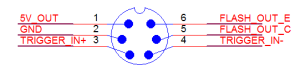
GPIO Trigger interface introduction
|
Trigger Serial No |
1 |
2 |
3 |
4 |
5 |
6 |
|
Cable Color |
Red |
Black |
Yellow |
White |
Gray |
Brown |
|
Function |
5V OUT/5V IN |
GND |
TRIGGER_IN+ |
TRIGGER_IN- |
FLASH_OUT_C |
FLASH_OUT_E |
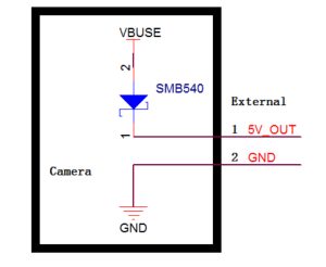
Power Supply
The camera is powered by USB2.0 BUS POWER, the power supply is 5V@500mA, The BUS POWER provide power supply to the camera, at the same time, it provides power supply via diode SMB540, the power is about 200mA@5V.
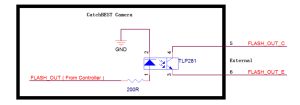
GPIO Input Interface
The following figure is the schematic diagram of external trigger input, the inputted signal has been insulated by opto-coupler TLP281.
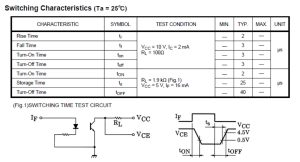
TLP281 conversion performance
The camera’s internal optocoupler VCC = 5V, if IF = 16mA, then the external trigger input Rising edge Delay is 2us, falling edge delay is 25us;
When using “TRIGGER_IN +” as trigger source, the trigger electrical level range is 0V- + 5V. If the trigger source electrical level is out of this range, an external current limiting resistor should be connected, the optocoupler works under current of 10mA. Limiting resistor is calculated as follows:
R = 100 x (Vin – 0.7) – R0
Vin is Trigger source electrical level
R0 is the camera’s internal series resistor 200 Ohm
R is the required external series resistor.
Under normal temperatures (0- + 50 degrees), the maximum operating current of the optocoupler is 50mA, standard operating current is 10mA, if it exceeds the maximum allowable current, optocouplers may be burned.

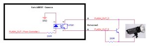
GPIO Output Interface (control flashlight)
For some flash light which has Rising edge input (We can measure the flash light pin to determine whether there is a Rising edge input, if we have measured a pin has electrical level signal, it can be judged there is Rising edge electrical level internal the flash light, such as the K-150A models flash light, one of the synchronous trigger pin end is + 5V, and the other end is GND), you can use the connection diagram below: