What is a fluorescence filter?
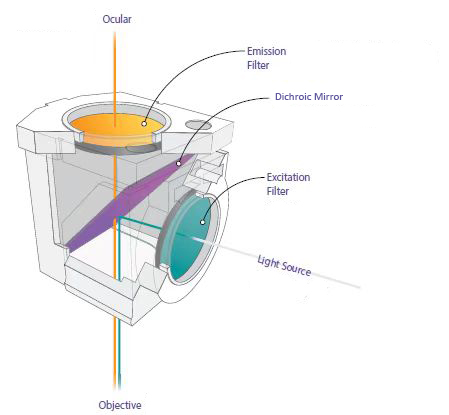 A fluorescence filter is an essential component in fluorescence microscope. A typical system has three basic filters: an excitation filter, an emission filter and a dichroic mirror. They are commonly packaged in a cube so that the group is inserted together into the microscope.
How does a fluorescence filter work?
Excitation Filter
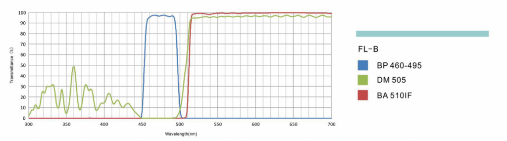
Excitation filters transmit light of a specific wavelength and block other wavelengths. They can be used to produce different colors by tuning the filter to allow only one color through. The excitation filters come in two main types — long pass filters and band pass filters. The exciter is usually a bandpass filter that passes only the wavelengths absorbed by the fluorophore, thus minimizing excitation of other sources of fluorescence and blocking excitation light in the fluorescence emission band. As shown by the blue line in the figure, BP is 460-495, which means that it can only pass through the fluorescence of 460-495nm.
It is placed within the illumination path of a fluorescence microscope and filters out all wavelengths of the light source except for the fluorophore excitation range. The filter minimum transmission dictates the brightness and brilliance of images. A minimum of 40% transmission for any excitation filter is recommended such that the transmission is ideally >85%. The bandwidth of the excitation filter should be entirely within the fluorophore excitation range such that the center wavelength (CWL) of the filter is as close as possible to the peak excitation wavelength of the fluorophore. The excitation filter optical density (OD) dictates the background image darkness; OD is a measure of how well a filter blocks the wavelengths outside of transmission range or bandwidth. A minimum OD of 3.0 is recommended but an OD of 6.0 or greater is ideal.
 Emission Filter
Emission filters serve the purpose of allowing the desirable fluorescence from the sample to reach the detector. They block shorter wavelengths and have high transmission for longer wavelengths. The filter type is also associated with a number, e.g. BA510IF in the figure (interference barrier filter), that designation refers to the wavelength at 50% of its maximum transmission.
The same recommendations for excitation filters hold true for emission filters: minimum transmission, bandwidth, OD, and CWL. An emission filter with the ideal CWL, minimum transmission, and OD combination provides the brightest possible images, with the deepest possible blocking, and ensures the detection of the faintest emission signals.
Dichroic Mirror
The dichroic mirror is placed between the excitation filter and emission filter at a 45° angle and reflects the excitation signal towards the fluorophore while transmitting the emission signal toward the detector. Ideal dichroic filters and beam splitters have sharp transitions between maximum reflection and maximum transmission, with a >95% reflection for the bandwidth of the excitation filter and a transmission of >90% for the bandwidth of the emission filter. Select the filter with the intersection wavelength (λ) of the fluorophore in mind, to minimize stray-light and a maximize the fluorescent image signal-to-noise ratio.
The dichroic mirror in this figure is the DM505, so named because 505 nanometers is the wavelength at 50% of the maximum transmission for this mirror. The transmission curve for this mirror shows high transmission above 505 nm, a steep drop in transmission to the left of 505 nanometers, and maximum reflectivity to the left of 505 nanometers but still may have some transmission below 505 nm.
What’s the difference between long pass and band pass filters?
Fluorescence filters can be divided into two types: long pass (LP) and band pass (BP).
Long pass filters transmit long wavelengths and block the shorter ones. The cut-on wavelength is the value at 50% of peak transmission, and all wavelengths above the cut-on are transmitted by the long pass filters. They are frequently utilized in dichroic mirrors and emission filters. Longpass filters should be used when the application requires maximum emission collection and when spectral discrimination is not desirable or necessary, which is generally the case for probes that generate a single emitting species in specimens with relatively low levels of background autofluorescence.
Band pass filters only transmit a certain wavelength band, and block others. They reduce crosstalk by allowing only the strongest portion of the fluorophore emission spectrum to be transmitted, reduce autofluorescence noise and thus improve the signal-to-noise ratio in high background autofluorescence samples, which long pass filters cannot offer.
How many types of fluorescence filter sets BestScope can supply?
Some common types of filters include blue, green, and ultraviolet filters. As shown in the table.
|
Filter Set |
Excitation Filter |
Dichroic Mirror |
Barrier Filter |
LED lamp Wave Length |
Application |
|
B |
BP460-495 |
DM505 |
BA510 |
485nm |
·FITC: Fluorescent antibody method ·Acidine orange: DNA, RNA ·Auramine: Tubercle bacillus ·EGFP, S657, RSGFP |
|
G |
BP510-550 |
DM570 |
BA575 |
535nm |
·Rhodamine, TRITC: Fluorescent antibody method ·Propidium iodide: DNA ·RFP |
|
U |
BP330-385 |
DM410 |
BA420 |
365nm |
·Auto-fluorescence observation ·DAPI: DNA staining ·Hoechest 332528, 33342: used for Chromosome staining |
|
V |
BP400-410 |
DM455 |
BA460 |
405nm |
·Catecholamines ·5-hydroxy tryptamine ·Tetracycline: Skeleton, Teeth |
|
R |
BP620-650 |
DM660 |
BA670-750 |
640nm |
·Cy5 ·Alexa Fluor 633, Alexa Fluor 647 |
Filter sets that are used in fluorescence acquisitions are designed around the major wavelengths used in fluorescence applications, which is based around the most used fluorophores. For this reason, they are also named after the fluorophore they are intended for imaging, such as DAPI (blue), FITC (green) or TRITC (red) filter cubes.
|
Filter Set |
Excitation Filter |
Dichroic Mirror |
Barrier Filter |
LED lamp Wave Length |
|
FITC |
BP460-495 |
DM505 |
BA510-550 |
485nm |
|
DAPI |
BP360-390 |
DM415 |
BA435-485 |
365nm |
|
TRITC |
BP528-553 |
DM565 |
BA578-633 |
535nm |
|
FL-Auramine |
BP470 |
DM480 |
BA485 |
450nm |
|
Texas Red |
BP540-580 |
DM595 |
BA600-660 |
560nm |
|
mCherry |
BP542-582 |
DM593 |
BA605-675 |
560nm |
How do you choose a fluorescence filter?
1. The principle of selecting fluorescence filter is to let the fluorescence/emission light pass through the imaging end as far as possible, and completely block the excitation light at the same time, so as to obtain the highest signal-to-noise ratio. Especially for the application of multiphoton excitation and total internal reflection microscope, the weak noise will also cause great interference to the imaging effect, so the requirement for signal to noise ratio is higher.
2. Know the excitation and emission spectrum of the fluorophore. To construct a fluorescence filter set that generates a high-quality, high-contrast image with a black background, excitation and emission filters should achieve high transmission with minimal passband ripple over the regions that correspond to the fluorophore excitation peaks or emissions.
3. Consider the durability of fluorescence filters. These filters must be impervious to intense light sources that generate ultraviolet (UV) light that could lead to “burnout”, particularly of the exciter filter as it is subjected to the full intensity of the illumination source.
The Different Fluorescence Sample Images
The resources are collected and organized on the Internet, and are only used for learning and communication. If there is any infringement, please contact us to delete.